All the pins on the Arduino, analog and digital pins can be used as outputs - all you need to do is use the "pinMode()" routine, usually in setup(), to configure the pin - for example to make digital pin 2 an output: pinMode(2, OUTPUT);
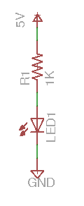
Sometimes it's useful to draw a picture of circuits, we call these "circuit diagrams" or "schematics" - here's a simple one:
Here the wiggly line "R1" represents a resistor  we write it's value "1K" next to it.
An LED is a semiconductor light, they come in lots of different colours - we use this symbol  for an LED. It is made from the symbol of a diode with some light coming out of it. Like diodes LEDs only work if they are in the correct way around - if you look closely at an LED you'll see that one lead on the LED is longer than the other - the longer lead is the one that comes out of the flat side of the triangle in the symbol,
the shorter one comes out of the point at the other end.
for an LED. It is made from the symbol of a diode with some light coming out of it. Like diodes LEDs only work if they are in the correct way around - if you look closely at an LED you'll see that one lead on the LED is longer than the other - the longer lead is the one that comes out of the flat side of the triangle in the symbol,
the shorter one comes out of the point at the other end.
Other symbols represent connections to ground ("GND", 0 volts)  or a voltage like 5 volts ("+5", or "5V")
In fact the circuit above is the circuit we built when we were introducing you to the prototyping boards:
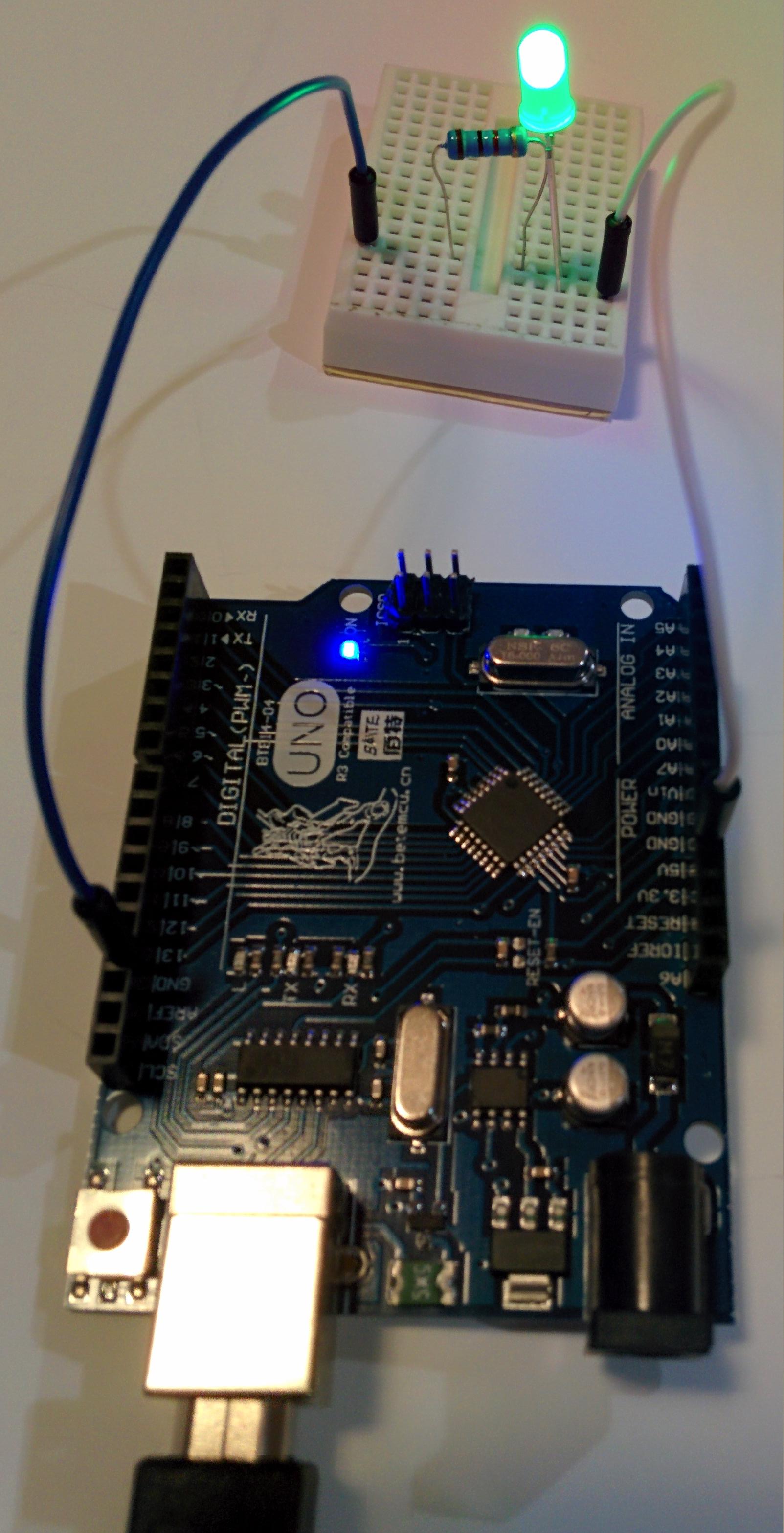
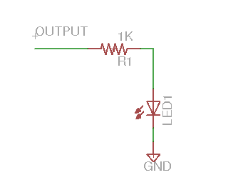
Your Arduino's output pins can only drive a small current without being damaged - that means you can drive a small, low current, LED through a current limiting resistor - instead of connecting your resistor to 5v hook it to an output pin like pin 2 you can turn the LED off or on by turning the output off and on.
In fact you've already done this, the circuit for the blue LED "L" on the arduino is the same, it's attached internally to pin 13 is just the same way. Open up the blink sketch and change the initialisation of the "led" variable to "2" instead of "13".:
	int led = 2;

	// the setup routine runs once when you press reset:
	void setup() {
  		// initialize the digital pin as an output.
  		pinMode(led, OUTPUT);
	}

	// the loop routine runs over and over again forever:
	void loop() {
  		digitalWrite(led, HIGH);   // turn the LED on (HIGH is the voltage level)
  		delay(1000);               // wait for a second
  		digitalWrite(led, LOW);    // turn the LED off by making the voltage LOW
  		delay(1000);               // wait for a second
	}
Load it up and try it out, you external LED should blink. Look at the program closely "pinMode(led, OUTPUT);" makes pin 2 an output during initialisation. "digitalWrite(led, HIGH);" makes pin 2 drive +5v to its output, and the LED goes on, "digitalWrite(led, LOW);" makes pin 2 drive 0v (GND) and the LED goes out.
What do you think this program does? try it out:
	int led1 = 12;
	int led2 = 2;

	// the setup routine runs once when you press reset:
	void setup() {
  		// initialize the digital pin as an output.
  		pinMode(led1, OUTPUT);
  		pinMode(led2, OUTPUT);
	}

	// the loop routine runs over and over again forever:
	void loop() {
  		digitalWrite(led1, HIGH);   // turn the LED on (HIGH is the voltage level)
  		digitalWrite(led2, LOW);
  		delay(1000);               // wait for a second
  		digitalWrite(led1, LOW);    // turn the LED off by making the voltage LOW
  		digitalWrite(led2, HIGH);
  		delay(1000);               // wait for a second
	}
Digital outputs can be off or on, but not half way on - so how can we dim an LED to half brightness?
Your arduino's digital outputs can be turned on and off very fast to do what's called "pulse width modulation", if you do it fast enough your eye won't see an LED flicker, if the pin is on more than it is off you LED will be brighter, if the pin is off more than it is on the LED will be dimmer.
Arduinos have aroutine you can call:
analogWrite(led, brightness);
"brightness" can be any value from 0 to 255 - 0 is off, 255 is always on, values in between will give varying degrees of brightness
The following program shows how you animate the brightness of an LED:
	/*
 	 Fade

	 This example shows how to fade an LED on pin 2
	 using the analogWrite() function.

	 This example code is in the public domain.
	 */

	int led = 2;           // the pin that the LED is attached to
	int brightness = 0;    // how bright the LED is
	int fadeAmount = 5;    // how many points to fade the LED by

	// the setup routine runs once when you press reset:
	void setup()  {
  	// declare pin 2 to be an output:
  		pinMode(led, OUTPUT);
	}

	// the loop routine runs over and over again forever:
	void loop()  {
		// set the brightness of pin 2:
		analogWrite(led, brightness);

		// change the brightness for next time through the loop:
		brightness = brightness + fadeAmount;

		// reverse the direction of the fading at the ends of the fade:
		if (brightness == 0 || brightness == 255) {
			fadeAmount = -fadeAmount ;
		}
		// wait for 30 milliseconds to see the dimming effect
		delay(30);
	}
This section describes how to do things using components that are not included in the kit
When Arduino pins are used as outputs they can only drive a small amount of current, it's why we use a 1K resistor when we drive LEDs directly, if we try and drive too much current the Arduino CPU will either not provide enough, or could be damaged. The same goes for voltage, if you want to drive something that needs a higher voltage you can't connect it directly to your Arduino, you will damage it.
If we want to use devices that use more power we can use a transistor like a TIP122 (you can find them at Jaycar down town) to drive other devices. Here are some examples:
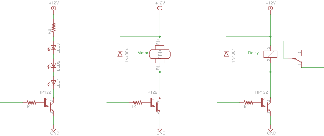
You can find a TIP122 datasheet here this will help you figure out which pin is which.
In each example the "base" terminal (pin 1) of the transistor is driven from an Arduino pin (on the left) through a 1K resistor - transistors like this one are current driven, a small amount of current between the "base" and "emitter" terminals (pin 1 and pin 3) causes a large current to flow between the "collector" terminal (pin 2) and the emitter.
In all the examples above change the "+12v" voltage to match the voltage you need, this circuit will work for anything up to about 50V.
The diagram on the left shows how to drive multiple LEDs that need a higher voltage, or a single big bright LED that needs a lot of current - what value should you use for the resistor R2? Here's an article that can help you decide.
A DC motor pulls way too much current for an Arduino to drive directly, the middle diagram shows how you can drive one - notice the 1N4004 diode across the motor, when you switch a motor off it can generate a voltage that can damage the transistor - the diode protects it - you can also find 1N4004 diodes at Jaycar.
The diagram on the right shows how you can drive a relay from an Arduino - a relay is a switch that is turned on and off by an electromagnet, again because the relay has a coil you need a 1N4004 protection diode. You use a relay because you want to switch a high current or voltage circuit, or because you want to isolate your Arduino from another circuit. You should not be designing circuits that use more than about 50v (like mains voltages), they can be very dangerous.
(if you want to use a motor to go forwards and backwards, you may instead want to use a motor controller)
You can buy multicoloured LEDs individually or as strips:

You can drive short ones directly from your Arduino and make every LED a different colour. Ada calls the "NeoPixels" and has an excellent guide on how to use them.