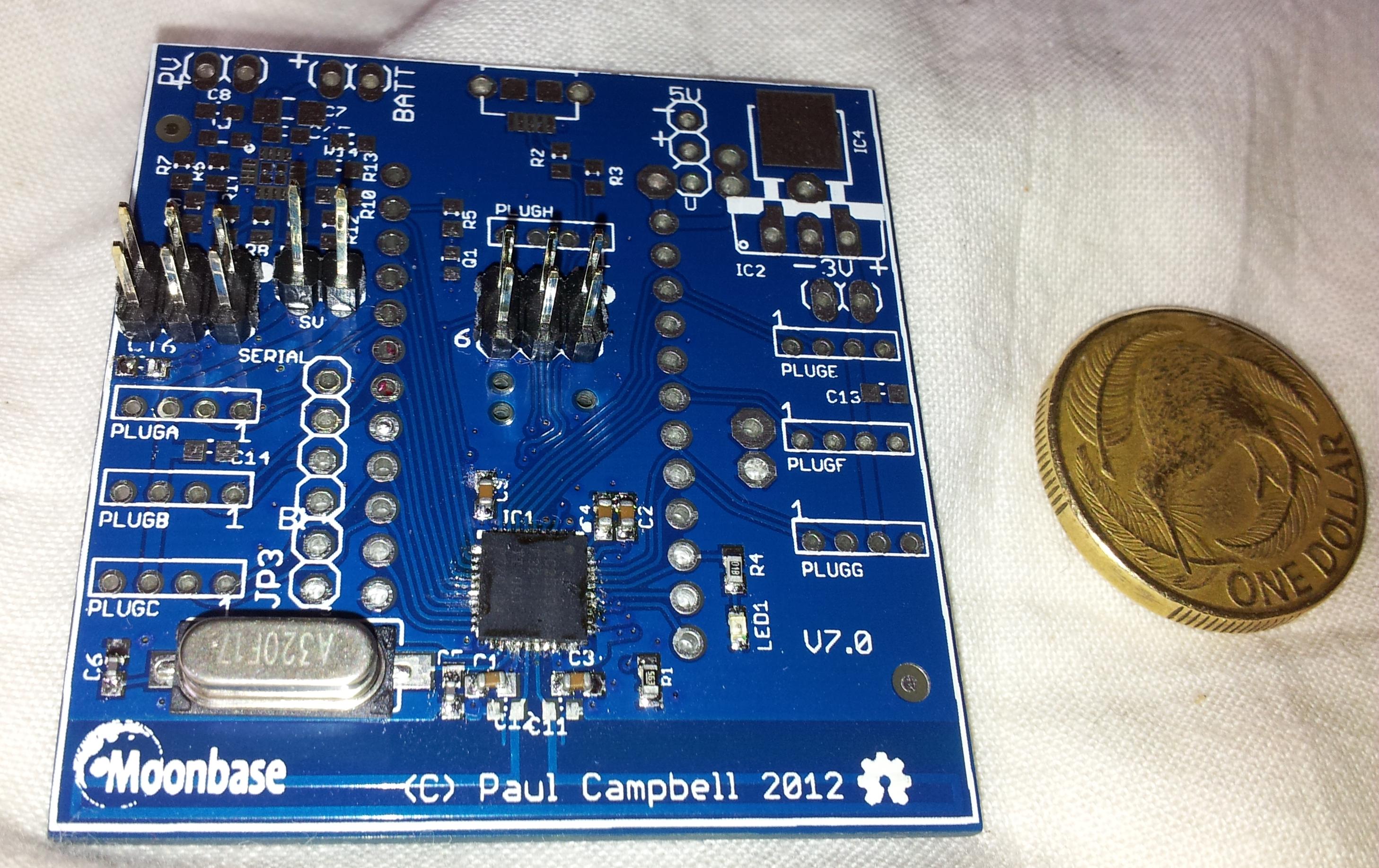
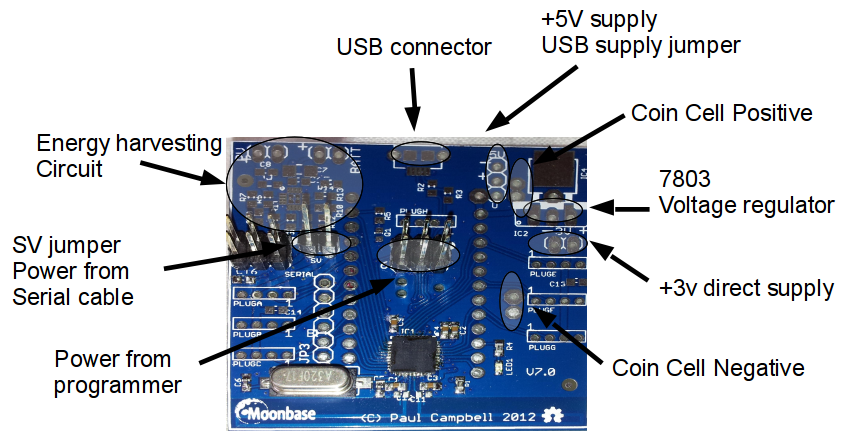
Our first development board is 5cm square, because we don't know how you will use it we provide it with the basic surface mount parts in place but the various headers not soldered in place. There are many options here, some components are not supplied (for example if you want to power it from a USB connector you'll need to buy a USB socket and a 3V voltage regulator)
The board has a folded dipole antenna etched along one side, this means you can't put the board in a sealed metal box - don't mount anything metalic near this edge of the board - for best omnidirectional results mount all the boards with the dipole edge mounted vertically.
We expect you will almost certainly want to solder the central 3x2 programmer header in place and maybe one of the serial connectors, there are also spots for connectors compatible with Seeed's grove sensors, we include a couple of connectors.
NOTE: this is the final prototype, the production board will have minor documentation and layout changes, mounting holes, and space to add A/D converters.
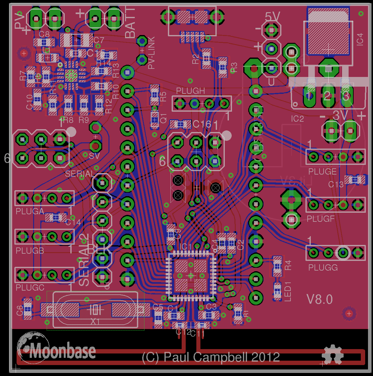
Schematic and layout - click for larger images:
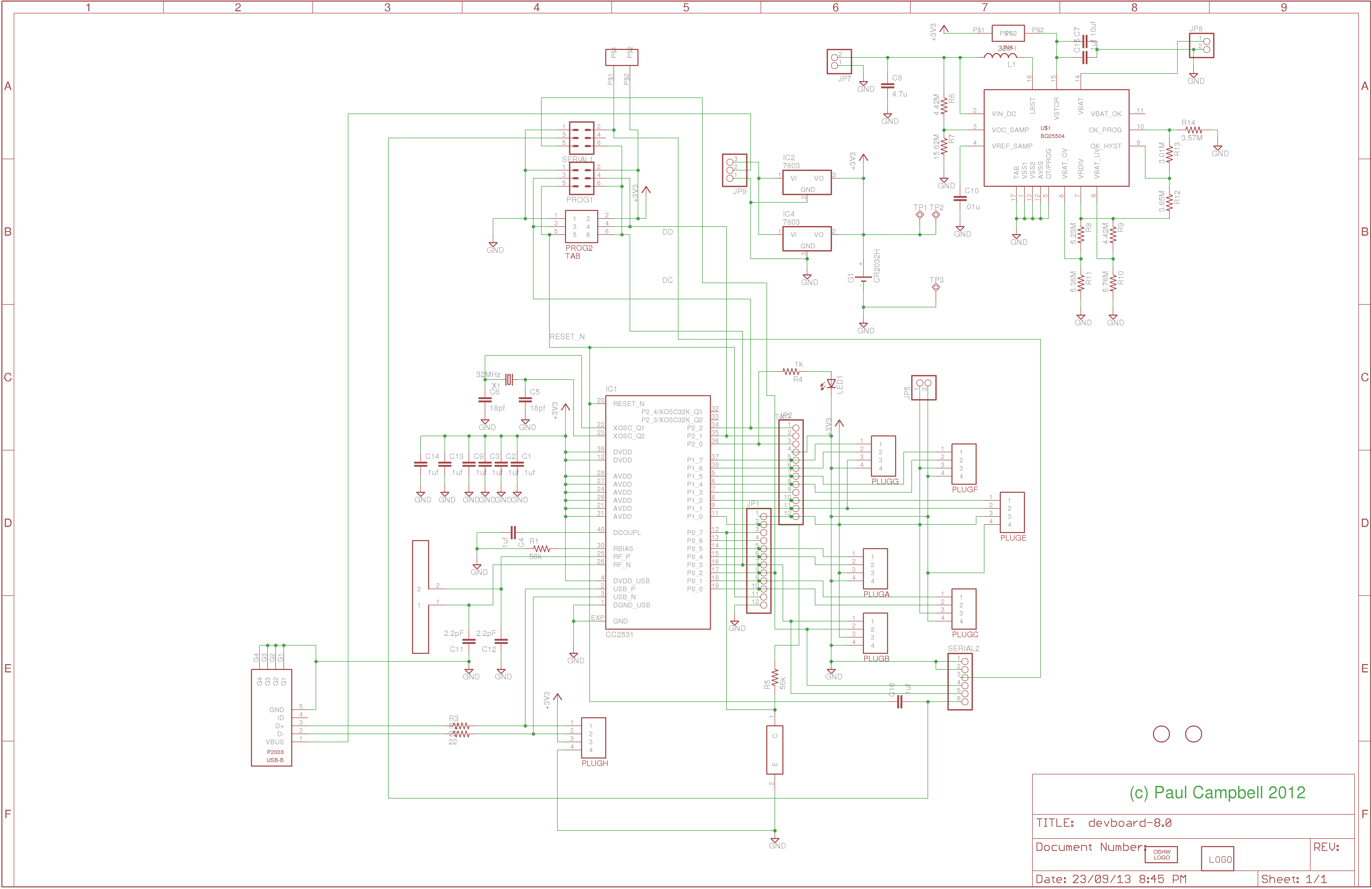
The main programming/debug connector is the 3x2 pin header in the middle of the board, connect it to the programmer pin 1 to pin 1, just below it there's also a TAB-Connect connector, program it from below.
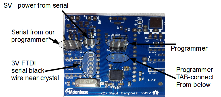
There are three options for serial connectors:
There are lots of different ways to power the development board. Be careful to make sure that at any one time you are powered from one source, if you are programming disconnect any batteries, etc
You can build a serial gateway by:
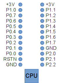
CC2533s have 3 multibit ports P0, P1, and P2. P0 and P1 have 8 bits while P2 has 5 bits. Bits are denoted P0.0 .... P0.7, P1.0, ....
Almost all the GPIOs are available for hookup on the two long 12-pin vertical lines of holes shown in the images above - you can install your own headers (not provided) in them or solder wires directly. Note pins P2.4 and P2.5 (the hardware I2C controller) are only available through PLUGH.
There are also spots available for 2mm sockets (PLUGA-PLUGH) compatible with Seeed's Grove sensors - each connector has 4 pins - power, ground and two data pins. PLUGG is special - it's powered from P1.1 a high power output pin capable of sourcing up to 20mA, this means you can power down a device when it isn't being used. They are connected:
| Plug | Pin 1 | Pin 2 | Pin 3 | Pin 4 |
| PLUGA | P1.5 | P1.4 | +3V | GND |
| PLUGB | P0.3 | P0.2 | +3V | GND |
| PLUGC | P0.1 | P0.0 | +3V | GND |
| PLUGE | P1.2 | P1.1 | +3V | GND |
| PLUGF | P1.5 | P1.4 | +3V | GND |
| PLUGG | P1.7 | P1.6 | P1.1 | GND |
| PLUGH | P2.5 | P2.4 | +3V | GND |
Note that the 2 pins in PLUGH are the hardware I2C controller. The 2 pins in PLUGB are the serial uart0.
In addition pin P2.0 is connected to the on-board LED - on power up it will be lit weakly through the on-chip pullups - make this port an output and write a 0 to this port to turn it off and save power, write a 1 to turn it on.
Finally there are pads for an on board daylight sensor - (R5/Q1 - not provided) this is powered up P1_0 and sensed on P0.7.
Note: there are lots of options here, some are potentially mutually exclusive - look carefully before you make choices - make sure that the pins you want to use are not already being used for some other function (for example: if you try and use P0.2 and P0.3 as GPIOs you may collide with their more likely use as serial input/output).
Downloads
The Eagle board design files can be downloaded from here: